The need for smaller wings to achieve faster flight is a popular belief, although efforts to fly faster often result in a considerable loss of performance.
- Why are different surfaces identified in paragliding? Vertical surface and total surface
- What do they mean? What do they do?
- How do we identify them? Can a comparison of real surface area and vertical surface area give us an idea of performance and speed?
A parachute carries us, but who carries the parachute?
Forces on the wing
Consider a conversation between two pilots;
- I fly with a 24m2 wing, so I can fly much faster.
- Although the area of my wing is 27 m2, its speed is good. We are at the same speed as you.
The argument that a smaller wing is needed to fly faster is a common argument, although the desire to fly fast can often result in a major loss of performance.
If you look a little closer, you may notice that both pilots fly with the same wing. The areas mentioned on the subject they talk about are the projected areas for one, and the flat area for the other. In other words, they fly with the same size and same model wings.
You can experience discussions like this in every flight zone.
- Why are several surfaces defined for the paraglider? Vertical surface and total surface
What are their meanings and what are they for? - How are they defined, how can we get an idea of performance and speed by comparing the actual surface area and the vertical surface area?
- What is the “good” surface to consider in our two friends when we talk about flight speed?
Paraglider, a three-dimensional wing:
In fact, compared to other fixed wing gliders, or light class flying machines such as delta wing, the paraglider has a strong three-dimensional wing.
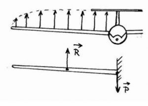
This oddity stems directly from the specific mechanical structure of our parachutes, very different from conventional wings. In a glider or rigid wing, for example, the resistance of aerodynamic forces is provided by one or more beams, lifting through the span. This boom behaves like a beam embedded in the center of the Wing, and often Bending, the sum of the forces reported in the center of the Wing, or the aerodynamic result is equal to the weight balance of the aircraft (Figure 1).
Figure 1: glider wing, bending beam
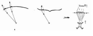
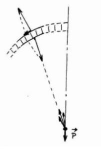
On a paraglider wing, no rigid part is likely to support the efforts of lift in flexion to transfer them to the pilot level. Only a set of lines, do not being able to take back only pure traction forces, is available for the transfer of forces. The breakdown of local lift elements at each line point is shown in figure 2, first approximating the paraglider to a simple surface, and assuming that the local lift is always positive.
Figure 2: Paraglider with ropes loaded.
This divergence and its consequences on the structure mainly depend on the average curvature of the wing, the center of flight (vault) and the pilot position, the suspension line with respect to the center of curvature of the convergence point on the center of the arch. The local force vector on the fabric tension can occur at different angles depending on the force vector along the ropes and the Wing-ropes-Pilot system.
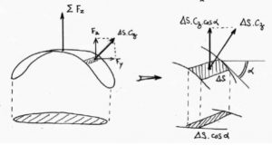
From a general point of view, several situations may arise (Figure 3):